
Wählen Sie eine
oder mehrere Sprachen aus
0,1,0
- Deutsch
- Englisch
- Chinesisch
- Spanisch
Schwingkreis
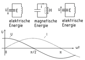
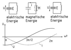
Ein Schwingkreis ist eine Schaltung mit Induktivität und Kapazität, bei dem die enthaltene Energie abwechselnd im magnetischen Feld der Spulen und dem elektrischen Feld der Kondensatoren gespeichert ist. Haupteinsatzgebiete von Schwingkreisen sind Frequenzfilter und Blindleistungskompensation.
Grundsätzlich unterscheidet man zwischen Reihen- und Parallelschwingkreis. Bei einem Reihenschwingkreis sind Induktivität und Kapazität in Reihe geschaltet. Das bedeutet, sie werden vom selben Strom durchflossen. Bei sinusförmiger Anregung eilt die Spannung am Kondensator um 90° nach, während sie an der Spule um 90° voreilt. Die Gesamtspannung ist demnach stets kleiner als die größere Einzelspannung und beträgt im Resonanzfall (${X_L} = {X_C}$) Null Volt.
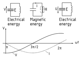
Im Parallelschwingkreis liegen Induktivitäten und Kapazitäten an einer identischen Spannung. Das Bild zeigt den Strom- und Spannungsverlauf bei einer Erregung mit sinusförmiger Wechselspannung. Zum Zeitpunkt $\omega t = 0$ist der Kondensator aufgeladen ($u = \hat u$), der Spulenstrom ist Null. Die Spannung am Kondensator baut sich ab und erzeugt einen Spulenstrom. Im Punkt $\pi /2$ist der Kondensator vollständig entladen und das Spulenmagnetfeld bricht zusammen. Die Selbstinduktionsspannung der Spule erzeugt einen Strom, der den Kondensator mit entgegengesetzter Polarität auflädt. Am Zeitpunkt $\pi $ ist der Kondensator vollständig negativ geladen. Der Schwingkreis funktioniert jetzt mit umgekehrter Polarität analog zum Zeitbereich von 0 bis $\pi $. Bei $2\pi $ hat er seinen Ausgangszustand erneut erreicht.
Bei einer verlustlos angenommenen Schaltung verläuft diese Schwingung mit konstanter Amplitude. In realen Schaltungen mit Widerstandsverlusten ergibt sich eine gedämpfte Schwingung.
Resonant circuit
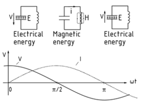
A resonant circuit consists of an inductor and a Capacitor in which the energy is stored alternately in the magnetic field of the coils and the electric field of the capacitors. Main areas of application for resonant circuits are frequency filters and reactive Power compensation.
A distinction is made between series resonant circuits and parallel resonant circuits. In a series resonant circuit, the inductor and capacitor are connected in series, i.e. the same current flows through them. In the case of sinusoidal excitation, the voltage at the capacitor lags by 90°, while the voltage at the coil leads by 90°. Therefore, the total voltage is always less than the higher individual voltage and, in the case of Resonance (${X_L} = {X_C}$), is zero volts.
In a parallel resonant circuit, the inductors and capacitors exhibit identical voltage. The image below shows the current and voltage profiles for excitation with sinusoidal alternating current. When $\omega t = 0$, the capacitor is in a charged state ($u = \hat u$), the coil current is zero. The voltage at the capacitor reduces and generates a coil current. At $\pi /2$, the capacitor is completely discharged and the coil's magnetic field breaks down. The coil's self-induced voltage generates a current that charges the capacitor with opposing polarity. At $\pi$, the capacitor is fully negatively charged. The resonant circuit now works with reverse polarity in the same way as the time period from 0 to $\pi$. At $2\pi$, the circuit has returned to its original state.
,In a theoretical, loss-free circuit, this Oscillation takes place at a constant amplitude. Real circuits involving Resistance losses give rise to damped oscillation.
谐振电路
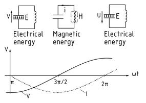
谐振电路包括一个电感器和一个电容器,其中能量被交替地存储在线圈的磁场和电容器的电场中。谐振电路的主要应用领域是频率滤波器和无功功率补偿。
可分为串联谐振电路和并联谐振电路。在串联谐振电路中,电感器和电容器串联连接,即相同的电流流过它们。在正弦激励情况下,电容器上的电压滞后 90°,而线圈上的电压领先 90°。因此,总电压总是低于单独的较高电压,并且在共振 ( ${X_L} = {X_C}$ )情况下,总电压是零伏。
在并联谐振电路中,电感器和电容器的电压相同。下面的图像表示了在正弦交流电激励情况下的电流和电压概况。当 $\omega t = 0$ 时,电容器处于充电状态( $u = \hat u$ ),线圈电流为零。然后电容器上的电压降低并产生线圈电流。当 $\pi /2$ 时,电容完全放电,线圈的磁场消失。线圈的自感应电压产生的电流与电容器的充电电流具有相反极性。当 $\pi$ 时,电容器完全带负电荷。谐振电路与从 0 到 $\pi$ 时间周期内的电路以同样方式工作,但极性相反。当 $2\pi$ 时,该电路返回其原始状态。
从理论上讲,无损耗电路中振荡幅度保持恒定。涉及电阻损耗的实际电路产生阻尼振荡。
揩振电路 0 -π
揩振电路 π - 2 π
近义词
串联谐振电路
并联谐振电路
Circuito resonante
Un circuito resonante consiste en un inductor y un capacitor en los cuales la energía es almacenada de manera alternativa en el campo magnético de las bobinas y el campo eléctrico de los capacitores. Las principales áreas de aplicación de los circuitos resonantes son los filtros de frecuencia y la compensación de energía reactiva.
Se debe distinguir entre los circuitos de resonancia en serie y los circuitos de resonancia en paralelo. En un circuito de resonancia en serie, el inductor y el capacitor están conectados en serie, es decir, la misma corriente fluye a través de ellos. En el caso de la excitación sinusoidal, el voltaje en el capacitor se desfasa 90°, mientras que el voltaje en la bobina se adelanta 90°. Por lo tanto, el voltaje total siempre es menor que el voltaje individual más alto y, en el caso de la resonancia ( ${X_L} = {X_C}$ ), es de cero voltios.
En un circuito de resonancia en paralelo, los inductores y capacitores presentan un voltaje idéntico. La siguiente imagen muestra los perfiles de corriente y voltaje para la excitación con corriente alterna sinusoidal. Cuando $\omega t = 0$, el capacitor está en un estado de carga ( $u = \hat u$ ), la corriente de la bobina es cero. El voltaje en el capacitor se reduce y genera una corriente de bobina. En $\pi /2$, el capacitor está completamente descargado y el campo magnético de la bobina se descompone. El voltaje autoinducido de la bobina genera una corriente que carga el capacitor en la polaridad opuesta. En $\pi$, el capacitor es cargado completamente de manera negativa. El circuito de resonancia ahora funciona con polaridad inversa, de la misma manera que el periodo de tiempo de 0 a $\pi$. En $2\pi$, el circuito ha regresado a su estado original.
En un circuito teórico libre de pérdidas, esta oscilación se lleva a cabo con una amplitud constante. Los circuitos reales que involucran pérdidas de resistencia dan lugar a la oscilación amortiguada.
Circuito resonante 0 a ?
Circuito resonante ? a 2 ?
