Choose one
or multiple languages
0,1,1
- German
- English
- Chinese
- Spanish
Measuring bridge
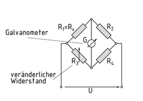
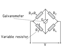
Measuring bridges are circuits used to measure electrical parameters such as Capacitance and Resistance. They are essentially formed by the parallel connection of two voltage dividers (series connections). The accuracy of measurements depends solely on the Tolerance of the components used.
A measuring bridge is balanced in such a way that the potentials between the series connections are the same. The current in the bridge arm is then zero. The following applies in the case of a measuring bridge with four resistors: $\frac{{{R_1}}}{{{R_2}}} = \frac{{{R_3}}}{{{R_4}}}$.
If one resistance value (R1) is unknown but the other three values are known, it can be determined by modifying R3 until the galvanometer displays zero. The missing value is then calculated using the formula ${R_x} = {R_3}\frac{{{R_2}}}{{{R_4}}}$.
In addition to the Wheatstone's bridge illustrated, other models such as the Thomson's bridge, the Maxwell-Wien bridge, the Wien-Robinson bridge and the Schering bridge are available.
Measuring bridges based on the above-mentioned Design can also be used to determine impedances and reactances.
Messbrücke
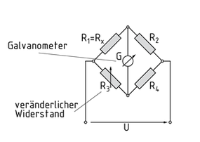
Messbrücken sind Schaltungen zur Messung von elektrischen Größen wie Kapazitäten oder Widerständen. Sie bestehen im Wesentlichen aus der Parallelschaltung von zwei Spannungsteilern (Reihenschaltungen). Die Genauigkeit der Messungen ist nur von der Toleranz der verwendeten Bauteile abhängig.Eine Messbrücke wird so abglichen, dass die Potentiale zwischen den Reihenschaltungen den gleichen Wert haben. Dann ist der Strom im Brückenzweig Null. Bei einer Messbrücke mit vier Widerständen gilt $\frac{{{R_1}}}{{{R_2}}} = \frac{{{R_3}}}{{{R_4}}}$. Ist ein Widerstandswert unbekannt (R1), lässt er sich bei Kenntnis der anderen drei Widerstände ermitteln, indem R3 so lange verändert wird, bis das Galvanometer den Wert Null anzeigt. Mit ${R_x} = {R_3}\frac{{{R_2}}}{{{R_4}}}$ wird anschließend der gesuchte Widerstandswert errechnet.Neben der abgebildeten Wheatstone'schen Messbrücke gibt es noch andere Varianten wie die Thomson-Brücke, Maxwell-Wien-Brücke, Wien-Robinson-Brücke oder die Schering-Brücke. Mit Messbrücken lassen sich nach dem oben beschriebenen Muster auch Schein- und Blindwiderstände bei Wechselschaltungen bestimmen.
测量电桥
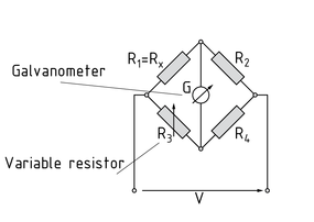
测量电桥是用于测量如电容和电阻等电参数的电路。基本上是由两个分压器(串联连接)并联而得。测量的准确度仅取决于所使用组件的公差。
以这样一种方式平衡测量电桥串联之间的电位。然后电桥臂的电流变为零。下面的测量电桥带有四个电阻: $\frac{{{R_1}}}{{{R_2}}} = \frac{{{R_3}}}{{{R_4}}}$ .
如果一个电阻值( $R_1 $ )是未知的,但其他的三个值是已知的,可以通过修改 $R_3 $ 直到检流计显示为零来确定值。然后使用公式 ${R_x} = {R_3}\frac{{{R_2}}}{{{R_4}}}$ 计算缺少的值。
除了所示的惠斯顿电桥,其他模型还有汤姆逊电桥、麦克斯韦-维恩电桥、文氏电桥和西林电桥。
根据上述设计的测量桥梁也可以用来确定阻抗和电抗。
测量电桥的结构
近义词
电阻测量
惠斯顿电桥
Puente de medición
Los puentes de medición son circuitos usados para medir parámetros eléctricos como la capacitancia y la resistencia. Se forman esencialmente por la conexión en paralelo de dos divisores de voltaje (conexiones en serie). La precisión de las mediciones depende únicamente de la tolerancia de los componentes usados.
Un puente de medición es equilibrado de manera tal que los potenciales entre las conexiones en serie son los mismos. La corriente en un brazo de puente es entonces cero. Lo siguiente aplica en el caso de un puente de medición con cuatro resistores: $\frac{{{R_1}}}{{{R_2}}} = \frac{{{R_3}}}{{{R_4}}}$.
Si un valor de resistencia ( $R_1 $ ) es desconocido pero los otros tres valores son conocidos, se puede determinar modificando $R_3 $ hasta que el galvanómetro muestre cero. El valor faltante es entonces calculado usando la fórmula ${R_x} = {R_3}\frac{{{R_2}}}{{{R_4}}}$.
Además del puente de Wheatstone ilustrado, otros modelos como el puente de Thomson, el puente Maxwell-Wien, el puente Wein-Robinson y el puente Schering están disponibles.
Los puentes de medición basados en el diseño antes mencionado pueden también usarse para determinar impedancias y reactancias.
Estructura de un puente de medición
