
Seleccione uno
o más idiomas
0,1,3
- Alemán
- Inglés
- Chino
- Español
Sistema de control de bucle cerrado
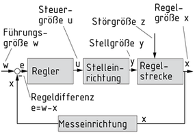
Un sistema de control de bucle cerrado es un dispositivo técnico diseñado para mantener automáticamente una variable controlada x en un valor definido, el valor de referencia w. Su característica principal es su acción de bucle cerrado, es decir, la retroalimentación de la variable controlada x y la comparación entre la variable controlada y la variable de referencia. El objetivo del sistema de control de bucle cerrado es usar un actuador para minimizar la desviación de control e, incluso bajo la influencia de las variables de perturbación.
Hay número de controladores disponible para optimizar la respuesta de control.
Controlador P: El valor de salida cambia proporcionalmente a la desviación de control.
Controlador I: El controlador muestra una respuesta de salida integradora, es decir, la desviación de control es corregida completamente en el estado estático.
Controlador D: El valor de salida es determinado por la velocidad en la que el error de control cambia. Este tipo de controlador se usa solo en combinación con otros elementos de control.
A menudo, se combinan controladores individuales para mejorar la respuesta de control del sistema. Los controladores continuos resultantes se nombran de acuerdo con la combinación de los elementos de control:
Controlador PI
Controlador PD
Controlador PID
Además de los controladores continuos antes mencionados, también se usan los controladores discontinuos (por ejemplo, controladores difusos, de dos posiciones o de tres posiciones) con variables de salida en etapas.
Los controladores de estado están entre los dispositivos usados para las tareas de control más complejas.
Diagrama de bloque de un bucle de control
Regelung
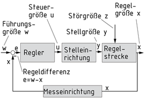
Die Regelung ist eine technische Einrichtung, um eine Regelgröße x automatisch auf einem definierten Wert, der Führungsgröße w, zu halten. Kennzeichnend für die Regelung ist der geschlossene Wirkungsablauf, also eine Rückführung der Regelgröße x und ein Vergleich zwischen Regelgröße und Führungsgröße. Ziel der Regelung ist es, über eine Stelleinrichtung die Regeldifferenz e auch bei Einwirken von Störgrößen zu minimieren.
Um ein möglichst gutes Regelverhalten zu erzielen, gibt es verschiedene Regler.
Oftmals werden einzelne Regler kombiniert, so dass sich ein besseres Regelverhalten des Systems ergibt. Die so entstandenen stetigen Regler heißen entsprechend der Kombination der Regelglieder:
- PI-Regler
- PD-Regler
- PID-Regler
Neben den oben angeführten stetigen Reglern kommen auch Unstetige Regler (zum Beispiel Fuzzy-, Zweipunkt- oder Dreipunktregler) zum Einsatz, bei denen die Ausgangsgrößen gestuft sind.
Für komplexere Regelaufgaben finden unter anderem Zustandsregler Verwendung.
Closed-loop control system
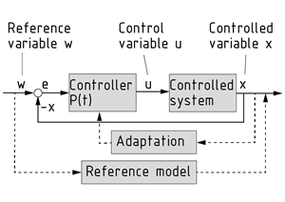
A closed-loop control system is a technical device designed to automatically keep a Controlled variable x at a defined value - the reference variable w. Its characteristic feature is its closed-loop action, i.e. feedback of the controlled variable x and comparison between controlled variable and reference variable. The aim of the closed-loop control system is to use an Actuator to minimise the control deviation e - even under the influence of disturbance variables.
A number of controllers are available to optimise the control response.
Individual controllers are often combined to improve the system's control response. The resultant Continuous controllers are named according to the combination of control elements:
- PI controller
- PD controller
- PID controller
In addition to the above-mentioned continuous controllers, Discontinuous controllers (e.g. fuzzy, two-position or three-position controllers) with stepped output variables are also used.
State controllers are among the devices used for more complex control tasks.
闭环控制系统
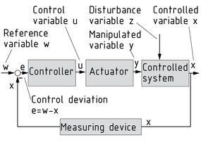
闭环控制系统是为了将受控变量 x 自动保持在规定值或者说参考变量 w 而设计的技术设备,它的特点就是其闭环操作,也就是说,受控变量 x 的反馈和参考变量和受控变量之间的比较。闭环控制系统的目的是利用执行机构(即使是有干扰量的影响的情况下),尽量减少控制偏差 e 的大小。
可用来进行优化控制响应的控制器有许多。
比例控制器:输出值根据控制偏差的大小按比例改变。
积分控制器:控制器具有综合输出响应,即在静态情况下,控制偏差可以得到完全矫正。
微分控制器:输出值由控制误差的变化的速度来确定。这种类型的控制器仅与其它控制元件组合使用。
各种控制器经常组合使用以提高系统的控制响应。组合后的连续控制器会根据控制元件的组合进行命名:
比例-积分 (PI) 控制器
比例-微分 (PD) 控制器
比例-积分-微分 (PID) 控制器
除了上述的连续控制器外,系统也可使用阶梯输出变量的不连续的控制器(例如模糊,两位置或三位置控制器)。
在对更复杂的控制任务进行控制的装置中,也可使用状态控制器。
控制回路的框图
